roomba 960 owners manual
Roomba 960 Owners Manual: A Comprehensive Guide
This manual details setup, operation, maintenance, and troubleshooting for your iRobot Roomba 960, ensuring optimal cleaning performance and a seamless user experience.
Welcome to the world of effortless cleaning with the iRobot Roomba 960! This Wi-Fi connected robot vacuum is designed to intelligently navigate and thoroughly clean your floors with minimal intervention. The Roomba 960 utilizes advanced features like Smart Mapping and Imprint Technology to learn your home’s layout and adapt to your cleaning preferences.
This comprehensive guide will walk you through every aspect of owning and operating your Roomba 960, from initial setup and daily use to advanced customization and troubleshooting. Prepare to experience a cleaner home and more free time with this innovative cleaning solution!
Unboxing and Initial Setup
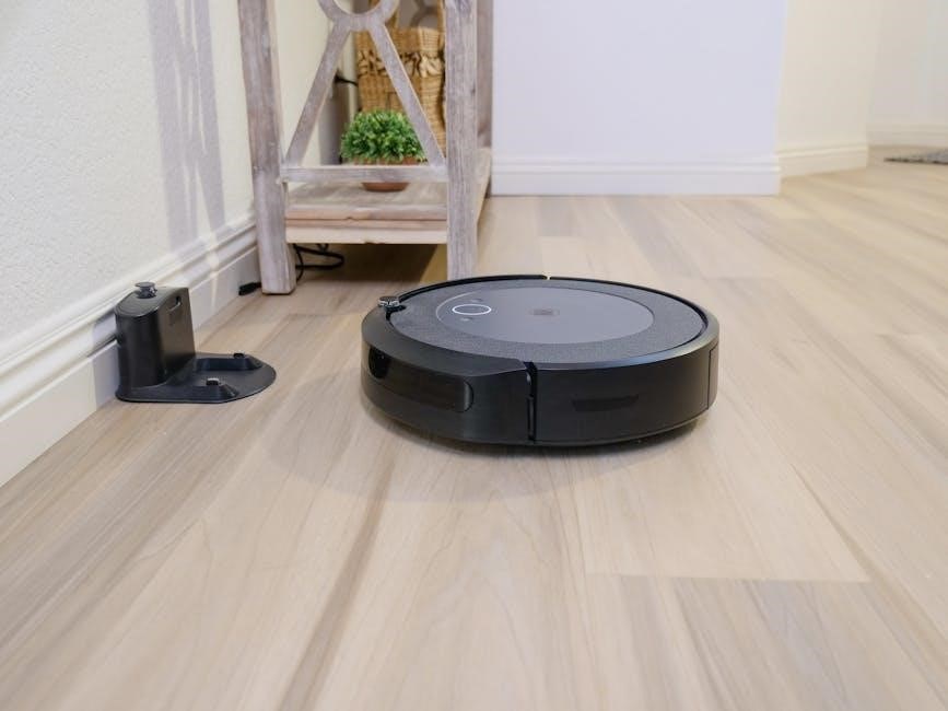
Carefully unpack your Roomba 960 and verify all components are present: the Roomba 960 robot, the Home Base charging station, and the power adapter. Before first use, it’s crucial to activate the battery. Remove the pull tab located under the Roomba. Place the Home Base on a level surface against a wall, ensuring ample space around it.
Connect the power adapter to the Home Base and plug it into a wall outlet. Download the iRobot HOME App to your smartphone or tablet to unlock the full potential of your Roomba 960 and begin the Wi-Fi connection process.
Component Overview
Your Roomba 960 package includes several key components. The Roomba 960 Robot itself features advanced navigation and cleaning technology. The Home Base Charging Station serves as the robot’s charging and docking location, ensuring it’s always ready for a cleaning cycle.
A Power Adapter is provided to connect the Home Base to a standard wall outlet. Understanding each component’s function is vital for proper setup and operation. Familiarize yourself with the robot’s buttons, sensors, and the Home Base’s indicator lights for a smooth experience.
The Roomba 960 Robot
The Roomba 960 is a Wi-Fi connected robot vacuum designed for efficient floor cleaning. It boasts a premium 3-Stage Cleaning System, effectively lifting dirt, dust, and debris. Key features include its advanced navigation using vSLAM® technology, creating a smart map of your home.
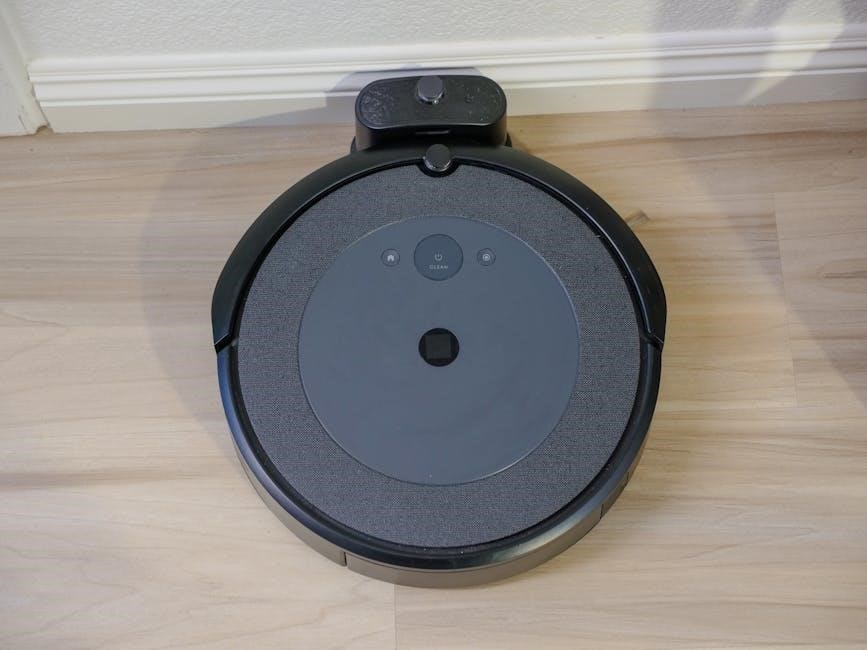
The robot features a high-efficiency filter to trap allergens. Buttons on top control basic operations, while full functionality is unlocked via the iRobot HOME App. Regularly inspect the brushes, extractors, and sensors for optimal performance and longevity.
The Home Base Charging Station
The Home Base serves as the Roomba 960’s charging and docking station. It provides a consistent power source, ensuring the robot is always ready to clean. Position the Home Base against a wall on a level surface with ample clear space around it – at least 3 feet on either side and 6 feet in front.
The station communicates with the Roomba, initiating charging when the robot returns automatically. Ensure a stable Wi-Fi connection for optimal functionality and app control. Avoid placing the Home Base on dark-colored carpets.
Power Adapter
The Roomba 960 utilizes a specific power adapter for charging via the Home Base. This adapter converts standard wall outlet power into the appropriate voltage for the robot’s battery. Always use the provided iRobot power adapter to avoid damaging the Roomba or creating a safety hazard.
Ensure the adapter is securely plugged into both the Home Base and a functioning wall outlet. Do not use damaged cords or adapters. The adapter’s specifications are detailed on its label; verify compatibility before use.
Getting Started: First-Time Use
Before enjoying automated cleaning, a few initial steps are crucial. First, activate the Roomba 960’s battery – a necessary step before its maiden voyage. Next, download the iRobot HOME App to your smartphone or tablet; this app unlocks advanced features and control.
Connecting your Roomba to your home Wi-Fi network is also essential for utilizing smart mapping and scheduling. Follow the in-app instructions for a seamless connection. Proper setup ensures optimal performance and access to all functionalities.
Activating the Battery
Prior to the first cleaning cycle, battery activation is a mandatory step. The Roomba 960 ships with the battery partially charged to prevent degradation during storage. To activate, simply place the robot on the Home Base charging station.
Allow the Roomba to charge uninterrupted for a minimum of 30 minutes, though a full charge (up to 120 minutes) is recommended for peak performance. A solid white light indicates a fully charged battery, signaling readiness for operation. This ensures optimal cleaning power from the start.
Downloading the iRobot HOME App
Unlock the full potential of your Roomba 960 by downloading the iRobot HOME App. Available for free on both iOS and Android devices, this app provides complete control over your robot vacuum. Search for “iRobot HOME” in the App Store or Google Play Store to locate and install the application.
The app enables scheduling, customized cleaning settings, map management, and access to valuable insights regarding cleaning performance. Creating an iRobot account is required for app functionality and robot registration.
Connecting to Wi-Fi
Establishing a Wi-Fi connection is crucial for utilizing the smart features of your Roomba 960. Open the iRobot HOME App and follow the on-screen instructions to connect your robot to your home’s 2.4 GHz Wi-Fi network. Ensure your smartphone is connected to the same network during the setup process.
The app will guide you through entering your Wi-Fi password and completing the connection. A stable Wi-Fi signal is essential for reliable operation and access to features like remote control and firmware updates.
Operating Your Roomba 960
Your Roomba 960 offers versatile cleaning options to suit your needs. Utilize the iRobot HOME App to select from various cleaning modes, including Auto, Spot Clean, and Manual control. Schedule cleaning cycles to automate floor care, setting specific days and times for operation. The physical Clean button on the robot initiates an immediate cleaning session.
Explore advanced features like Smart Mapping to define cleaning zones and Keep Out areas, optimizing cleaning efficiency and preventing access to restricted spaces.
Cleaning Modes Explained
The Roomba 960 provides several cleaning modes for tailored results. Auto Cleaning mode systematically cleans entire floors. Spot Clean focuses on a concentrated area, ideal for spills. Manual Control allows direct navigation via the iRobot HOME App.
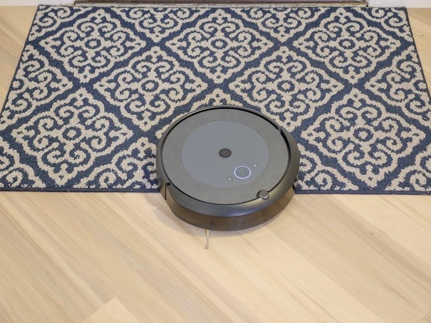
Power Preservation Mode extends runtime by reducing suction. The 960 intelligently adapts to floor types, maximizing cleaning effectiveness on carpets and hard floors. Understanding these modes ensures you leverage the robot’s capabilities for optimal cleaning performance and a consistently tidy home.
Scheduling Cleaning Cycles
The iRobot HOME App simplifies scheduling cleaning cycles for your Roomba 960. You can set specific days, times, and cleaning modes for automated cleaning. Create a customized schedule to fit your lifestyle, ensuring a consistently clean home without manual intervention.
The app allows for multiple schedules, accommodating varying cleaning needs throughout the week. Easily adjust or cancel schedules as needed, providing flexibility and control. Consistent scheduling maximizes the Roomba’s efficiency and maintains a spotless living environment.
Using the Clean Button
The “Clean” button on your Roomba 960 initiates an immediate cleaning cycle. A single press starts the robot on a general cleaning routine, navigating your floors efficiently. This is ideal for quick cleanups or when a scheduled cycle isn’t sufficient.
Pressing the Clean button again during a cycle will pause the Roomba. A subsequent press resumes cleaning from where it left off. This provides convenient control over the cleaning process. It’s a simple, direct method for initiating and managing cleaning sessions.
Maintenance and Cleaning
Regular maintenance is crucial for optimal Roomba 960 performance. This involves routinely emptying the dustbin to maintain suction power and cleaning efficiency. Additionally, inspect and clean the brushes to remove tangled hair and debris, ensuring effective floor coverage.
Filter cleaning is also essential; a clogged filter reduces suction. Following these simple steps extends the lifespan of your Roomba and guarantees consistently clean floors. Consistent upkeep prevents performance degradation and ensures reliable operation.
Emptying the Dustbin
To empty the dustbin, press the release button on the iRobot Roomba 960 and remove it carefully. Dispose of the collected debris into a trash receptacle, avoiding overfilling. Inspect the dustbin for any obstructions, like large items or tangled hair, and remove them.
Reinstall the dustbin securely until it clicks into place. Regular emptying, ideally after each cleaning cycle, maintains optimal suction and cleaning performance. A full dustbin significantly reduces cleaning effectiveness.
Cleaning the Brushes
Regularly cleaning the Roomba 960’s brushes is crucial for maintaining optimal performance. Remove the brush module and detach the brushes. Carefully remove any hair, fibers, or debris wrapped around the brush heads and end caps – a cleaning tool is helpful. Inspect the brush bearings for buildup and clear them if necessary.

Reinstall the brushes, ensuring they click securely into place. Clean brushes prevent tangling and ensure effective dirt pickup, extending the life of your Roomba and improving cleaning results.
Cleaning the Filters
Maintaining a clean filter is vital for your Roomba 960’s suction power and air quality. Remove the filter from the dustbin. Gently tap the filter to dislodge loose debris. Do not wash the filter; this can damage it. Inspect the filter for damage and replace it if necessary – typically every two months, depending on usage.
A clean filter ensures efficient dirt collection and prevents motor strain. Regularly checking and maintaining the filter contributes to optimal cleaning performance and prolongs the lifespan of your robot vacuum.
Troubleshooting Common Issues
Encountering problems with your Roomba 960? This section addresses frequent concerns. If your Roomba isn’t charging, ensure the Home Base is properly connected and the charging contacts are clean. For getting stuck situations, clear obstacles and check for tangled brushes.
Wi-Fi connectivity issues can often be resolved by restarting your router and Roomba. Consult the iRobot HOME app for specific error codes and solutions. Further assistance is available through iRobot’s customer support resources.
Roomba Not Charging
If your Roomba 960 isn’t charging, several factors could be at play. First, verify the Home Base is securely plugged into a working power outlet. Inspect the charging contacts on both the Roomba and the Home Base; clean them with a dry cloth to remove any dust or debris.

Ensure the Roomba is correctly positioned on the Home Base, making full contact. A faulty power adapter can also be the culprit – try a different outlet or adapter if possible. If issues persist, consult the iRobot support website.
Roomba Getting Stuck
If your Roomba 960 frequently gets stuck, identify common problem areas in your home. These include loose rugs, cords, and low-hanging furniture. Utilize Virtual Walls or Keep Out Zones within the iRobot HOME App to restrict access to these areas. Regularly clear clutter from floors to provide a clear path for the robot.
Inspect Roomba’s brushes for tangled hair or debris, as this can impede movement. Ensure the sensors are clean and unobstructed for optimal navigation. If the issue continues, review the troubleshooting section in the app.
Wi-Fi Connectivity Problems
Experiencing Wi-Fi issues with your Roomba 960? First, ensure your robot is within range of your Wi-Fi network. Restart both your Roomba and your router. Verify your Wi-Fi password is correct within the iRobot HOME App. Confirm your network is 2.4 GHz, as Roomba 960 doesn’t support 5 GHz networks.
Check for interference from other devices. If problems persist, try resetting the Roomba’s Wi-Fi connection through the app’s settings or consult the iRobot support resources for further assistance.
Advanced Features and Settings
Unlock the full potential of your Roomba 960 with its advanced features! Utilize Virtual Walls and Keep Out Zones within the iRobot HOME App to restrict cleaning in specific areas. Experience Smart Mapping, allowing Roomba to learn your home’s layout for efficient cleaning.
Imprint Technology remembers multiple floor plans. Customize cleaning settings – power, passes, and edge cleaning – directly within the app for a truly personalized cleaning experience. Explore these settings to optimize Roomba’s performance for your unique home.
Virtual Walls and Keep Out Zones
Define cleaning boundaries with ease! The Roomba 960 utilizes Virtual Walls, either physical barriers or digitally created zones within the iRobot HOME App, to prevent access to restricted areas. Keep Out Zones, managed entirely through the app, allow you to designate specific spaces – like pet bowls or delicate furniture – as no-go areas.
These features provide precise control over where Roomba cleans, protecting your belongings and ensuring efficient coverage of desired areas. Easily adjust and modify zones as your needs change.
Smart Mapping and Imprint Technology
Experience intelligent cleaning with advanced mapping! The Roomba 960 employs Smart Mapping to learn and remember your home’s layout, enabling systematic cleaning patterns and efficient navigation. This allows for targeted cleaning of specific rooms or zones.
Furthermore, Imprint Technology, accessible through the iRobot HOME App, remembers multiple floor plans, letting Roomba adapt its cleaning approach based on location. This feature optimizes cleaning routines and ensures a thorough clean throughout your entire home.
Customizing Cleaning Settings in the App
Take full control of your Roomba’s performance! The iRobot HOME App provides extensive customization options. Adjust cleaning modes – from quiet to max power – to suit different surfaces and messes. Schedule cleaning cycles for specific days and times, ensuring a consistently clean home.
You can also define Keep Out Zones and Virtual Walls directly within the app, preventing Roomba from entering restricted areas. Fine-tune cleaning passes and edge cleaning behavior for a truly personalized cleaning experience, all managed conveniently from your smartphone.
Technical Specifications
The Roomba 960 boasts advanced technology for superior cleaning; Dimensions are approximately 13.9 inches in diameter and 3.6 inches in height. It operates on a Lithium Ion battery, providing up to 120 minutes of runtime. The dustbin capacity is 0.6 liters.
Connectivity includes Wi-Fi (IEEE 802.11 b/g/n 2.4 GHz). It features a high-efficiency filtration system, capturing dust and allergens. The robot utilizes vSLAM® navigation for intelligent mapping and efficient cleaning paths, ensuring comprehensive coverage throughout your home.

Safety Information and Warnings

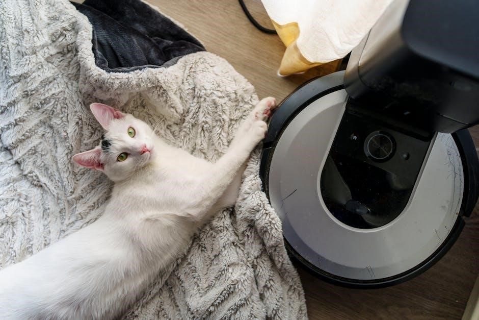
To ensure safe operation, always supervise children and pets during Roomba’s use. Avoid operating the robot over unsecured cords or loose rugs, as they may cause entanglement. Do not use Roomba to clean up flammable liquids or sharp objects.
Regularly inspect the brushes and cleaning head for damage. Disconnect the power adapter before performing any maintenance. Only use iRobot-approved batteries, chargers, and accessories. Do not disassemble or attempt to repair the robot yourself; contact customer support for assistance.
Warranty Information
iRobot provides a limited warranty covering defects in materials and workmanship for your Roomba 960. The warranty period typically begins from the date of original purchase. This warranty does not cover damage resulting from misuse, accidents, or unauthorized modifications.
To make a warranty claim, retain your proof of purchase and contact iRobot customer support. The warranty may include options for repair or replacement, at iRobot’s discretion. Extended warranties may also be available for purchase, offering additional coverage beyond the standard period.
Frequently Asked Questions (FAQ)
Q: Why isn’t my Roomba charging? A: Ensure the Home Base is properly connected and receiving power. Clean the charging contacts on both the robot and the base.
Q: How do I clean the Roomba’s sensors? A: Gently wipe the sensors with a clean, dry cloth. Dirty sensors can affect navigation.
Q: Can I use cleaning solutions with my Roomba? A: Avoid using harsh chemicals. Water is generally sufficient for damp mopping attachments, if applicable.
Customer Support and Resources
For immediate assistance, visit the iRobot website for a comprehensive knowledge base, troubleshooting guides, and helpful videos. You can also access the iRobot community forum to connect with other Roomba 960 owners and share experiences.
Direct customer support is available via phone or live chat. Detailed contact information, including regional support numbers, can be found on the iRobot website. Downloadable owner’s manuals and quick start guides are readily accessible for convenient reference.
Understanding Error Codes
Your Roomba 960 utilizes error codes to communicate issues, displayed either on the robot itself or within the iRobot HOME App. Common codes indicate brush obstructions, cliff sensor issues, or wheel malfunctions.
A comprehensive list of error codes and their corresponding solutions is available in the online owner’s manual and within the app’s troubleshooting section. Referencing these resources will help you quickly diagnose and resolve problems, minimizing downtime and ensuring optimal cleaning performance. Don’t ignore error messages!
Replacing Parts and Accessories
Maintaining peak performance for your Roomba 960 requires periodic replacement of wear-and-tear components. Key items include brushes (extractors and side brushes), filters, and occasionally, the battery.
Genuine iRobot replacement parts are recommended to ensure compatibility and optimal cleaning effectiveness. These can be purchased directly from the iRobot website or authorized retailers. Regularly inspect parts for damage and replace them as needed, following the instructions in the owner’s manual for proper installation and continued operation.
Firmware Updates
Keeping your Roomba 960’s firmware up-to-date is crucial for accessing the latest features, performance improvements, and bug fixes. Updates are typically delivered automatically over Wi-Fi through the iRobot HOME App.
The app will notify you when an update is available; ensure your Roomba is on the Home Base and connected to Wi-Fi to initiate the process. Do not interrupt the update, as this could damage the robot. Regularly checking for updates guarantees optimal functionality and a consistently enhanced cleaning experience.
Disposal and Recycling

Responsible disposal of your Roomba 960 and its components is essential for environmental protection. Do not dispose of the robot or its battery with general household waste.
Check local regulations for proper e-waste recycling options; iRobot encourages users to recycle responsibly, minimizing environmental impact. The battery contains potentially hazardous materials and requires special handling. Contact your local waste management authority for guidance on appropriate disposal methods, ensuring compliance with environmental standards.
iRobot HOME App Deep Dive
The iRobot HOME App unlocks the full potential of your Roomba 960. Beyond basic start/stop functionality, the app enables customized cleaning schedules, precise map management, and virtual wall creation.
Explore Imprint™ Smart Mapping for targeted cleaning zones and Keep Out Zones to restrict access. Adjust cleaning power, edge cleaning, and multiple passes for optimal results. Receive performance reports, access troubleshooting guides, and manage firmware updates directly through the app, enhancing your cleaning experience.
Maximizing Battery Life
To extend your Roomba 960’s runtime, ensure the battery is fully charged before each cleaning cycle. Regularly check and clean the charging contacts on both the robot and Home Base. Avoid excessively dusty or cluttered environments, as these increase energy consumption.
Utilize scheduling features to clean during off-peak hours, potentially reducing energy costs. Consider spot cleaning for smaller areas instead of full-house cleans when feasible. Proper filter maintenance also contributes to efficient operation and prolonged battery life.